Adding and Configuring the Switch
This was a little tricky because to access the webGUI of the switch the default IP is 192.168.0.1, however, that is the IP address of my Quantum Fiber Modem (and probably the default IP address of whatever ISP modem you’re using as well) which will result in pulling up the modem webGUI and not the one for the switch.
The workaround is to not plug the switch into the LAN port (re1) on pfSense yet, so make sure it is not connected to the
pfSense_Appliance. Power on the switch and connect your Admin_Device to port 5 on the switch. Go to configure your wired
network settings and set your IP address for the Wired or Ethernet connection to be on the same network as the switch:
192.168.0.x (I used 192.168.0.15). Set the Netmask to 255.255.255.0 and leave the Gateway blank for now.
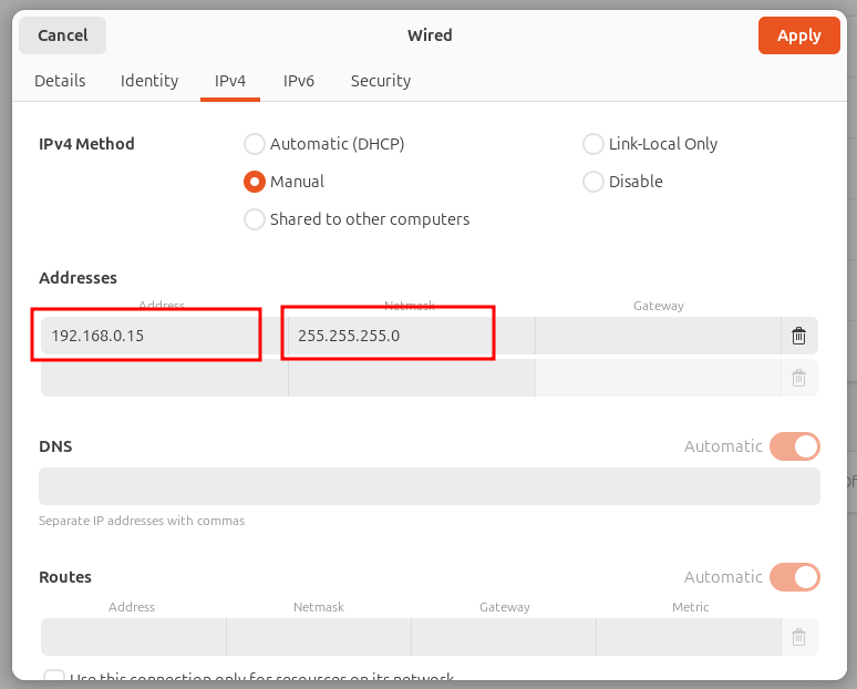
This is how it looks on Ubuntu settings. In Windows, you simply right click the internet connection icon in the tray in lower right-hand corner and select Network and Internet Settings. Click on Ethernet. In the section that starts with IP assignment it will have Automatic listed and an Edit button on the far-right of the section. Click Edit and select Manual from the drop down menu at the top and toggle on IPv4. Fill in the same fields as above.
Now in your web browser, navigate to 192.168.0.1 and you’re presented with a login page for the web console of the switch:
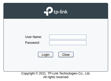
Use admin for User Name and admin for the Password. You’ll be immediately prompted to change the password, utilize your
password manager here.
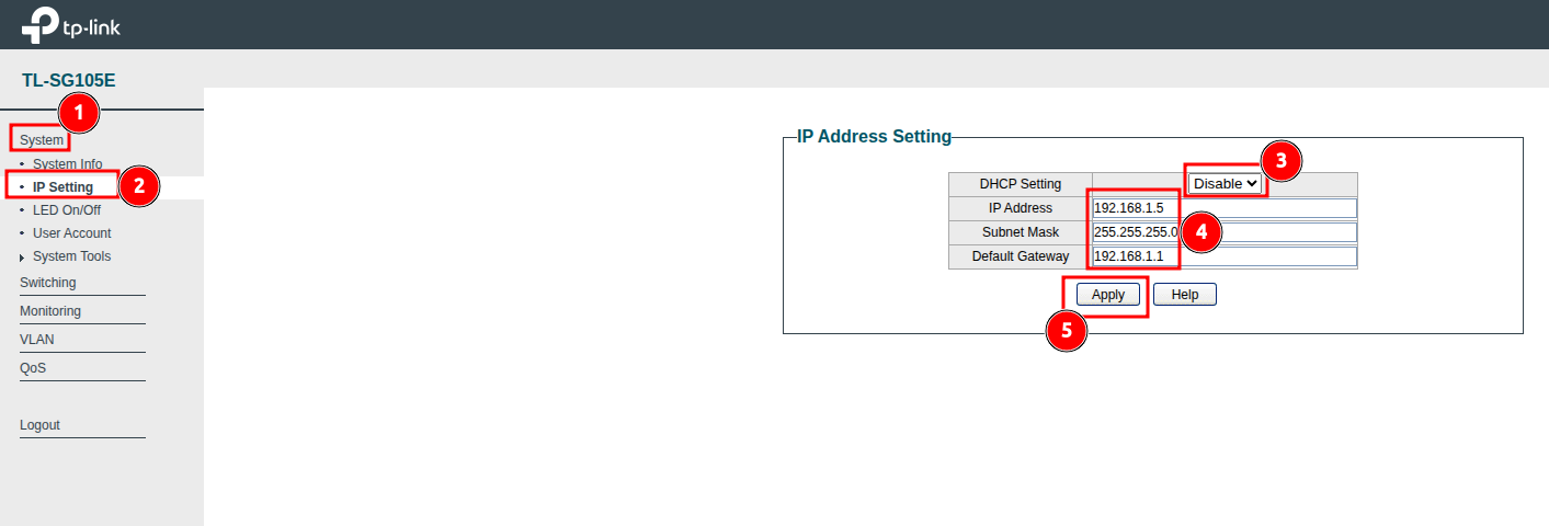
- Click System
- Click IP Setting
- Select Disable for DHCP Setting
- Change IP Address to
192.168.1.5, Subnet Mask to255.255.255.0and Default Gateway to192.168.1.1(our pfSense will be the Gateway that will route all networks on the switch to the internet) - Click Apply
Use an Ethernet cable to connect the LAN port on your pfSense_Appliance to Port 1 on the switch. Now close the web browser on
your Admin_Device and go back to your Internet and Network Settings for the Ethernet and for IPv4 change it from
Manual to Automatic. Disconnect and reconnect the Ethernet cable connecting you to Port 5 on the switch. When you reconnect,
pfSense DHCP LAN server should issue you an IP address automatically. Open the web browser and navigate to 192.168.1.5 and you
should be able to access the switch web console again.
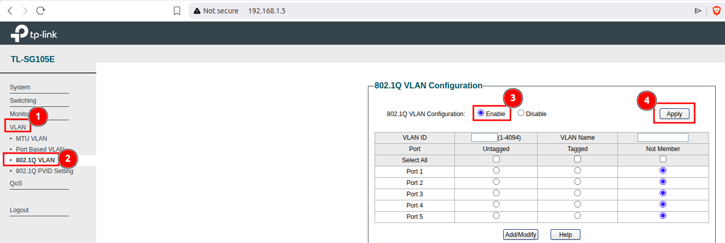
- Click VLAN
- Click 802.1Q VLAN
- Select Enable
- Click Apply
Next steps are on the same page:
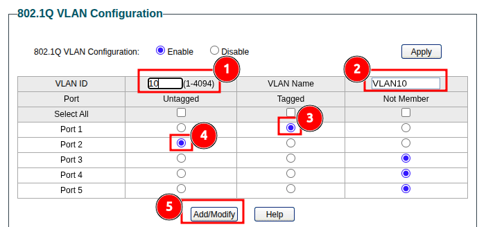
- For VLAN ID I used
10 - For VLAN Name I used
VLAN10 - For Port 1 select Tagged
- For Port 2 select Untagged and leave all others as Not Member
- Click Add/Modify
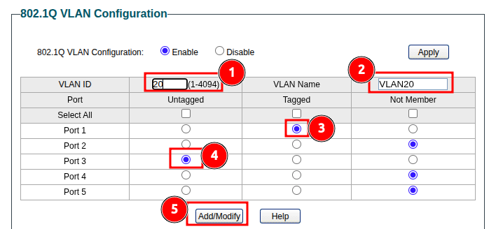
Repeat the same for VLAN20 but notice Port 3 is Untagged and Port 1 is Tagged, all others set to Not Member.
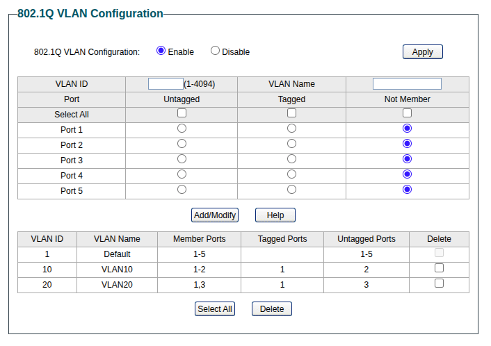
Your 802.1Q VLAN Configuration should look like this:
Now let’s add PVIDs:
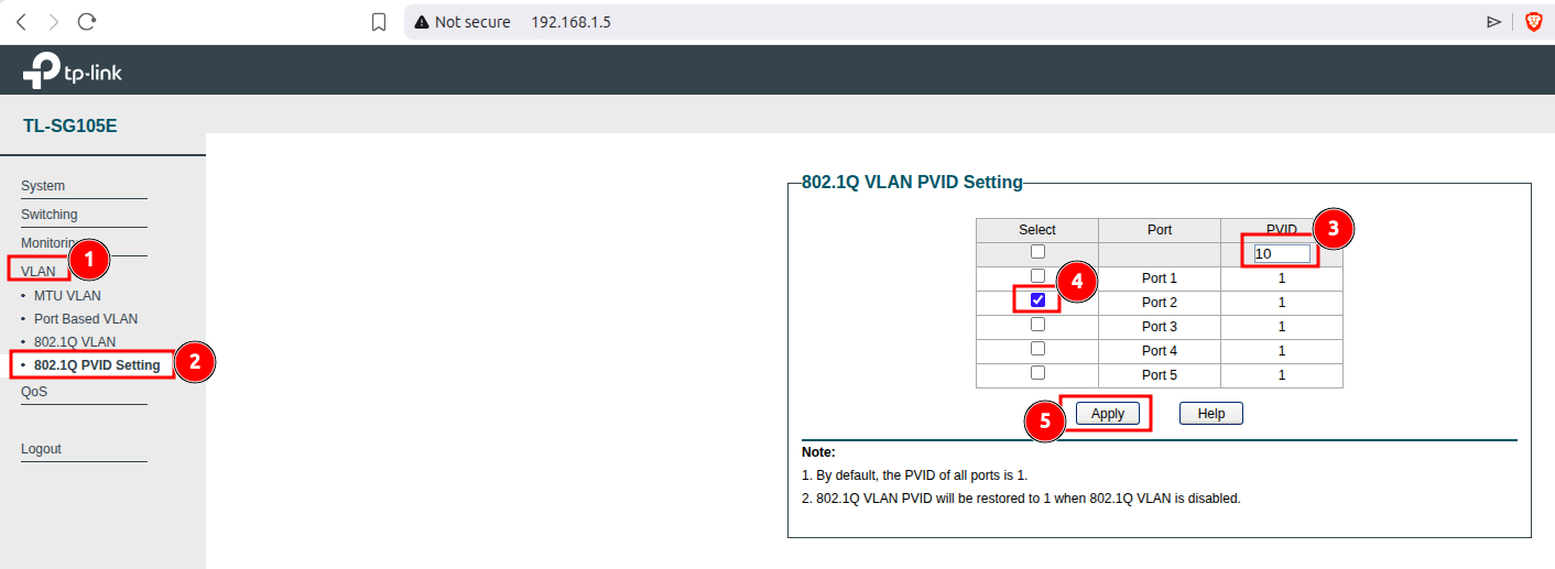
- Click VLAN
- Click 802.1Q VLAN PVID Setting
- Type
10in PVID - Check Port 2
- Click Apply
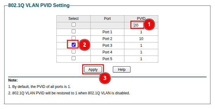
- Type
20in PVID - Check Port 3
- Click Apply
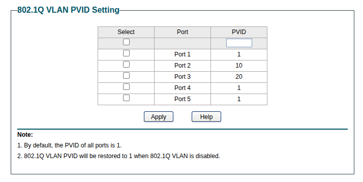
Your page should now look like this:
What did we just do? We created VLAN10 and VLAN20 on our switch. Because Port 1 will carry traffic from both VLANs to our
pfSense, we set Port 1 as Tagged on each VLAN, this way pfSense will know which traffic belongs to each VLAN since they
will be on the same cable. This means our switch will add additional information to each packet so that pfSense knows which port to
route it to. Because all traffic connected to Port 2 will be isolated to VLAN10, we can leave Port 2 as Untagged.
All other ports are not members of VLAN10 therefore they will not be able to reach devices in VLAN10. This same is repeated for
VLAN20 and Port 3.